методика построения для любой CAD системы
Про моделирование и печать шестеренок здесь написано достаточно. Однако, большинство статей предполагают использование спец. программ. Но, у каждого пользователя есть своя «любимая» программа для моделирования. Кроме того, не все хотят устанавливать и изучать дополнительный софт. Как же моделировать профиль зуба шестерни в программе, где не предусмотрено вычерчивание эвольвентного профиля? Очень просто! Но муторно… 🙂Нам понадобится любая программа, которая может работать с 2D графикой. Например, ваша любимая программа! Она работает с 3D? Значит и с 2D сможет! 😉 Строим профиль эвольвентного зуба без коррекции. Если кому-то захочется построить корригированный зуб, он может с этим разобраться самостоятельно. Информации полно — и в интернете, и в литературе. Если в вашей шестеренке зубьев больше 17-ти, то вам коррекция не понадобится. Если же зубьев 17 или меньше, то без коррекции возникает «утоньшение» ножки зуба, а при чрезмерной коррекции возникает заострение вершины зуба. Что выбрать? Решать вам.
1 шаг.
Определяем делительную окружность шестерни. Зачем это нужно? Чтобы определить межосевое расстояние. Т.е. где у вас будет располагаться одна шестерня, а где другая. Сложив диаметры делительных окружностей шестеренок и разделив сумму пополам, вы определите межосевое расстояние.
Чтобы определить диаметр делительной окружности нужно знать два параметра: модуль зуба и количество зубьев. Ну, с количеством зубьев – тут всем все понятно. Количеством зубьев на одной и другой шестерне определяется нужное нам передаточное отношение. Что такое модуль? Чтобы не связываться с числом «пи», инженеры придумали модуль. 🙂 Как вы знаете из курса школьной математики: D= 2 «Пи» R. Так вот, что касается шестеренок, там D = m* z, где D – это диаметр делительной окружности, m – модуль, z – количество зубьев. Модуль – величина, характеризующая размер зуба. Высота зуба равна 2,25 m. Модуль принято выбирать из стандартного ряда величин: 1; 1,25; 1,5; 2; 2,5; 3; 4; 5; 6; 8; 10; 12; 16; 20; 25; 32 (ГОСТ-9563). Можно ли придумать «свой» модуль? Конечно! Но ваша шестеренка будет нестандартная! 😉
2 шаг.
Чертим делительную окружность. У кого нет подходящей «проги», чертит на бумаге, фанере или металле! 🙂 От делительной окружности «откладываем» наружу на величину модуля (m) окружность вершин зубьев. Внутрь откладываем модуль и еще четверть модуля (1,25 m) — получаем окружность впадин зубьев. Четверть модуля дается на зазор между зубом другой шестерни и впадиной этой шестерни.
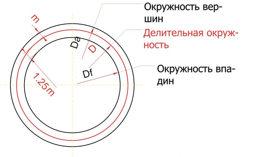
3 шаг:
Строим основную окружность. Основная окружность – это окружность, по которой «перекатывается» прямая линия, своим концом вычерчивая эвольвенту. Формула для расчета диаметра основной окружности очень простая: Db = D * cos a, где а – угол рейки 20 градусов. Эта формула нам не нужна! Все гораздо проще. Строим прямую линию через любую точку делительной окружности. Удобнее взять самую высокую точку, на «12 часов». Тогда линия будет горизонтальная. Повернем эту линию на угол в 20 градусов против часовой стрелки. Можно ли повернуть на другой угол? Думаю, можно, но не нужно. 🙂 Кому интересно, ищем в литературе или интернете ответ на вопрос.
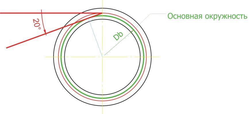
4 шаг:
Прямую линию, которую мы получили, будем поворачивать вокруг центра шестерни маленькими угловыми шагами. Но, самое главное, при каждом повороте против часовой стрелки будем удлинять нашу линию на длину той дуги основной окружности, которую она прошла. А при повороте по часовой стрелки наша линия будет укорачиваться на ту же величину. Длину дуги или мерим в программе, или считаем по формуле: Длина дуги = (Пи * Db * угол поворота (в градусах)) / 360
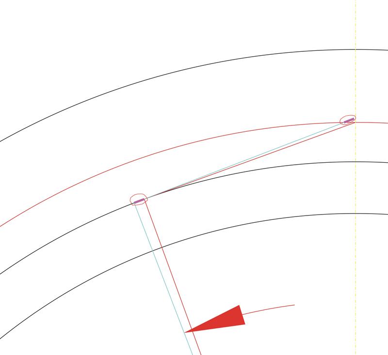
5 шаг
«Прокатываем» прямую линию по основной окружности с нужным угловым шагом. Получаем точки эвольвентного профиля. Чем точнее хотим строить эвольвенту, тем меньший угловой шаг выбираем.
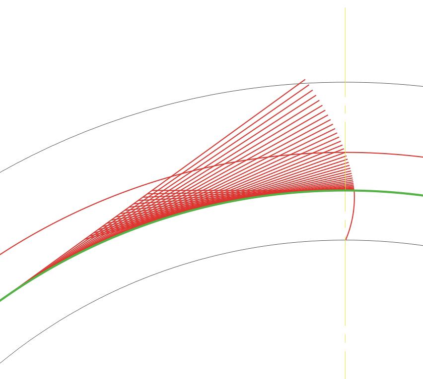 К сожалению, в большинстве программ автоматического проектирования (CAD) не предусмотрено построение эвольвенты. Поэтому эвольвенту строим по точкам либо прямыми, либо дугами, либо сплайнами. При построении эвольвента заканчивается на основной окружности. Оставшуюся часть зуба до впадины можно построить дугой того же радиуса, который получается на трех последних точках. Для 3D печати я рисовал эвольвенту сплайнами. Для лазерной резки металла мне пришлось рисовать эвольвенту дугами. Для лазера нужно создать файл в формате dwg или dxf (для некоторых, почему-то, только dxf). «Понимает» лазер только прямые, дуги и окружности, сплайны не понимает. На лазере можно сделать только прямозубые шестерни.
Делим окружность на такое количество частей, которое в 4 раза больше количества зубьев шестерни. Эвольвенту отзеркаливаем относительно оси зуба и копируем с поворотом нужное количество раз.
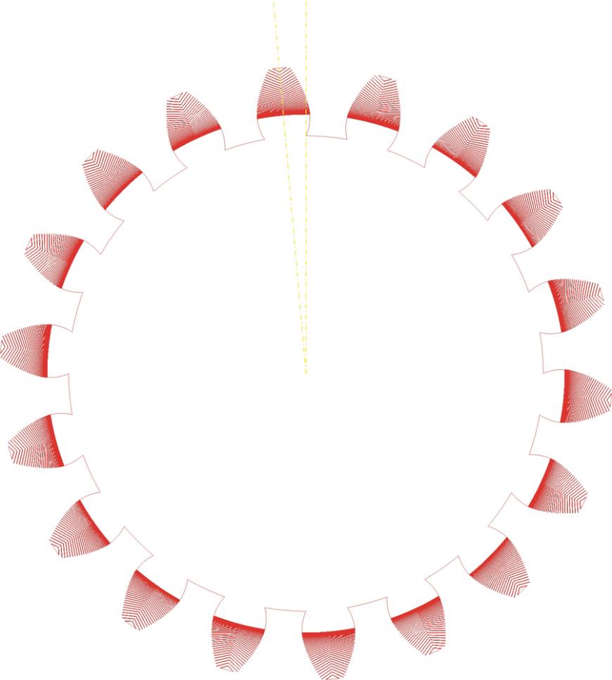
Чтобы получить шестерню в объеме, то задаем толщину и получаем прямозубую цилиндрическую шестерню:
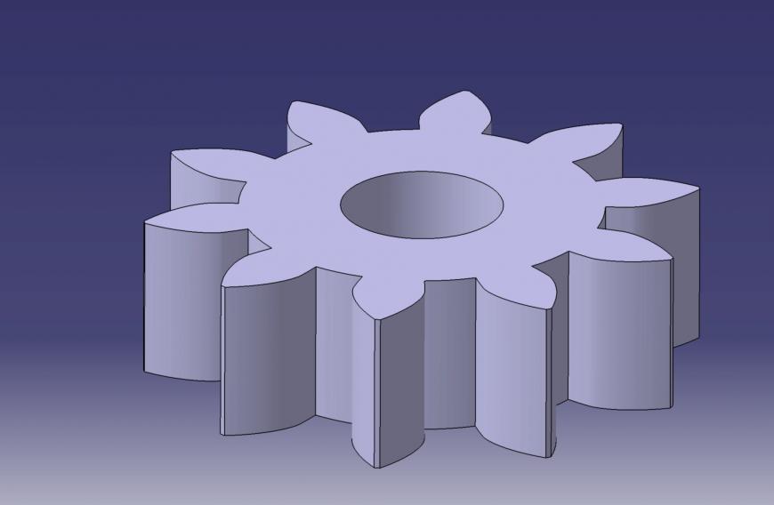
Если нужна косозубая шестерня, то вводим наклон зубьев и получаем:
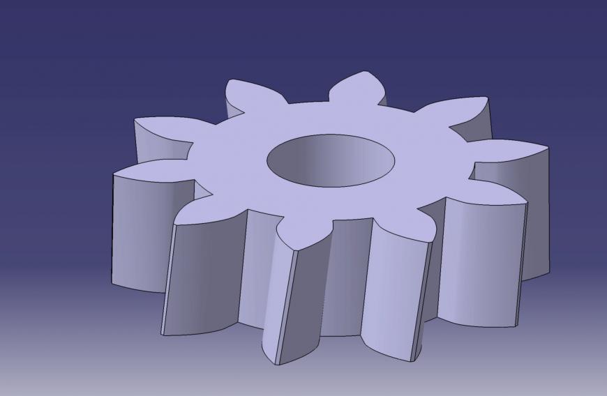
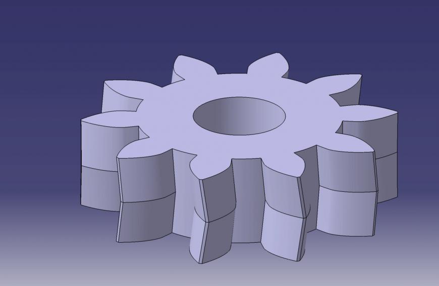
Для получения шевронной шестерни, нужно отзеркалить косозубую шестерню относительно нужной торцевой поверхности:
 Как смоделировать коническую шестерню, придумайте сами. 🙂
К вопросу о точности шестеренок. Те шестеренки, которые я распечатал на 3D принтере, сначала вращались, издавая легкое поскрипывание. Прошло некоторое время, и звук прекратился. Шестеренки «притерлись». 🙂
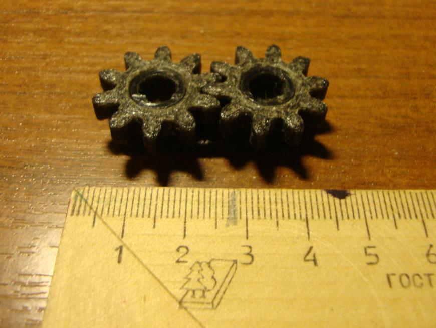 После модернизации принтера, шестеренки не печатал. Возможно, сейчас они напечатаются более точно, и не будут скрипеть.
Для вакуумной машины смоделировал пару – «шестерня-рейка». Их вырезали на лазере:
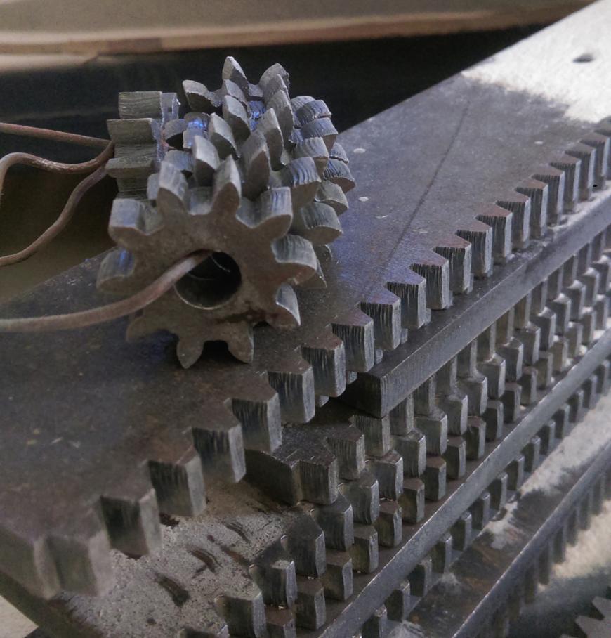 Рейка будет перемещать прижимную рамку с материалом (листовой АБС) из области нагрева в область вакуумного формования. Рейка и шестерня еще не испытывались. Возможно, придется «дорабатывать напильником». На рейке и шестерне видны «волны» от лазера – слишком толстый металл. Они то и могут заклинить. А, может, разработается. 🙂 Время покажет!
8.4: Передаточное отношение
Представьте себе велосипед: велосипедист обладает ограниченной мощностью, и хочет обеспечить максимальное использование этой мощности в любой момент времени.
Путем изменения механического преимущества изменяется скорость движения. Мощность представляет собой количество проделанной работы в единицу времени. Чем больше количество работы. тем ниже скорость ее выполнения.
Пример 8.1
В примере 8.1 показано, что если на стороне входа рычаг сместится на 1 метр, на стороне выхода рычаг сместится на 4 метра. Разница пропорциональна соотношению между длинами рычагов.
Длина на выходе / Длина на входе = 8 / 2 = 4
Интересно то, что оба расстояния преодолеваются за одно и то же время. Давайте представим, что смещение рычага на входе на 1 метр происходит за 1 секунду, так что скорость движения на входе составляет 1 метр в секунду. В то же время, на выходе смещение на 4 метра также происходит за 1 секунду, так что скорость движения здесь составляет 8 метров в секунду. Скорость на выходе БОЛЬШЕ скорости на входе за счет соотношения между длинами рычагов.
Пример 8.2
В примере 8.2 представлена та же система, что и в примере 8.1, но теперь на вход действует сила, равная 4 ньютонам. Какова равнодействующая сила на выходе?
Прежде всего, необходимо рассчитать приложенный момент в центре вращения, вызванный входной силой, с помощью формул из Блока 7:
Крутящий момент = Сила х Расстояние от центра гравитации = 4 Н х 2 м = 8 Н-м
Далее, необходимо рассчитать равнодействующую силу на выходе:
Сила = Крутящий момент / Расстояние = 8 Н-м / 8 м = 1 ньютон
Глядя на эти два примера, мы видим, что если система смещается на 1 метр под действием входной силы, равной 4 ньютона, то на выходе она сместится на 4 метра под действием силы, равной 1 ньютон. При меньшей силе рычаг смещается быстрее!
Мы можем видеть, как механическое преимущество (выраженное в форме рычагов) может быть использовано для управления входной силой в целях получения требуемого выхода. Передачи работают по тому же принципу.
Цилиндрическая прямозубая шестерня по сути представляет собой серию рычагов. Чем больше диаметр шестерни, тем длиннее рычаг.
Пример 8.3
Как видно из примера 8.3, результатом крутящего момента, приложенного к первой шестерне, является линейная сила, возникающая на кончиках ее зубьев. Эта же сила воздействует на кончики зубьев шестерни, с которой зацепляется первая шестерня, заставляя вторую вращаться по действием крутящего момента. Диаметры шестерен становятся длиной рычагов, при этом изменение крутящего момента равносильно соотношению диаметров. Если малые шестерни приводят в движение больше шестерни, крутящий момент увеличивается. Если большие шестерни приводят в движение малые шестерни, крутящий момент уменьшается.
Пример 8.4
В примере 8.4, если входная 36-зубая шестерня поворачивается на расстояние одного зуба (d = ширина 1 зуба), это означает, что она поворачивается на 1/36-ю своего полного оборота (а1 = 360 / 36 = 10 градусов). Поворачиваясь, она приводит в движение 60-зубую шестерню, заставляя последнюю смещаться также на 1 зуб. Тем не менее, для 60-зубой шестерни это означает смещение всего лишь на 1/60-ю полного оборота (а2 = 360 / 60 = 6 градусов).
Когда малая шестерня проходит определенное расстояние в заданный интервал времени, большая шестерня при этом проходить меньшее расстояние. Это означает, что большая шестерня вращается медленнее малой. Этот принцип работает в обоих направлениях. Если малые шестерни приводят в движение больше шестерни, скорость понижается. Если большие шестерни приводят в движение малые шестерни, скорость повышается.
Из примеров 8.1 — 8.4 видно, что отношение между размерами двух зацепляющихся между собой шестерен пропорционально изменению крутящего момента и скорости между ними. Это называется передаточным числом.
Как обсуждалось выше, количество зубьев шестерни прямо пропорционально ее диаметру, поэтому для расчета передаточного отношения вместо диаметра можно просто считать зубья.
Передаточное отношение выражается как (зубья ведущей шестерни) : (зубья ведомой шестерни), поэтому представленная выше пара шестерен может быть описана как 12:60 (или 36 к 60).
Передаточное число рассчитывается по формуле (зубья ведомой шестерни) / (зубья ведущей шестерни)
Поэтому передаточное число = зубья ведомой шестерни / зубья ведущей шестерни = 60/36 = 1,67
Как обсуждалось выше, передаточное отношение выражается как (зубья ведущей шестерни) : (зубья ведомой шестерни), так что пара шестерен, представленная выше, может быть выражена как 12:60 (или 12 к 60).
Передаточное число рассчитывается по формуле (зубья ведомой шестерни) / (зубья ведущей шестерни)
Поэтому передаточное число = Зубья ведомой шестерни / Зубья ведущей шестерни = 60/12 = 5
Глядя на пример, представленный выше…
Предельный перегрузочный момент второго вала может быть рассчитан по формуле:
Выходной момент = Входной момент х Передаточное число
Выходной момент = 1,5 Н-м х 5 = 7,5 Н-м
Свободная скорость второго вала может быть рассчитана по формуле:
Выходная скорость = Входная скорость / Передаточное число = 100 об/мин / 5 = 20 об/мин
Второй вал, таким образом, вращается со свободной скоростью 20 об/мин, при этом предельный перегрузочный момент равен 7,5 Н-м. При понижении скорости крутящий момент увеличивается.
Для второго примера расчеты могут быть произведены тем же способом.
Передаточное число = Зубья ведомой шестерни / Зубья ведущей шестерни = 12/60 = 0,2
Выходной момент = Входной момент х Передаточное число = 1,5 Н-м х 0,2 = 0,3 Н-м
Выходная скорость = Входная скорость / Передаточное число = 100 об/мин / 0,2 = 500 об/мин
Второй вал, таким образом, вращается со свободной скоростью 500 об/мин, при этом предельный перегрузочный момент равен 0,3 Н-м. При повышении скорости крутящий момент уменьшается.
Шестерня vs зубчатое колесо
Часто участникам портала приходится изготавливать зубчатые колеса и шестерни. Но мало кто задается вопросом, в чем их отличие?Недавно на полях одного топика, посвященного шестеренному насосу возник спор, что есть шестерня? Может ли быть две шестерни в паре? И чем шестерня отличается от зубчатого колеса, или это одно и то же?
Приводились разные мнения, перечислю некоторые —
1) Шестерни и зубчатые колеса — это одно и то же. Синонимы.
Вывод — те кто говорит, что изготовит ‘шестерни и зубчатые колеса’, на самом деле говорит ‘масло масляное’ и врет, что это разные вещи.
2) ШЕСТЕРНЯ
зубчатое колесо передачи с меньшим числом зубьев, а при равенстве их — ведущее зубчатое колесо.
Большой энциклопедический политехнический словарь, 2004
Почему так?
Согласно ГОСТ 16530-83 ‘Передачи зубчатые общие термины определения и обозначения’,
Шестерня — Зубчатое колесо передачи с меньшим числом зубьев.
При одинаковом числе зубьев зубчатых колес передачи шестерней называется ведущее зубчатое колесо.
Вывод — из двух зубчатых колес, работающих в паре, только одна называется шестерня, а второе — колесо. Шестерня, это то зубчатое колесо, которое, как правило, крутится с большей угловой скоростью.
3) Согласно ГОСТ 17398-72 ‘Насосы. Термины и определения’, Шестеренный насос —
Зубчатый насос с рабочими органами в виде шестерен, обеспечивающих геометрическое замыкание рабочей камеры и передающих крутящий момент.
Слово ‘шестерня’ в единственном числе этот ГОСТ не употребляет вообще, и определения понятия ‘шестерни’ также не содержит. Остается только попробовать вывести это определение из текста формулировки, от обратного:
Шестерни — рабочие органы зубчатого насоса, обеспечивающие геометрическое замыкание рабочей камеры и передающие крутящий момент.
Вывод — два рабочих органа, всегда работающих только в паре, этот ГОСТ называет шестернями, и их в единственном числе не бывает, как ножниц (если вынуть из насоса один рабочий орган, то он не станет шестерней, так как он один не может обеспечить геометрическое замыкание рабочей камеры и передавать крутящий момент согласно функции из ГОСТ 17398-72), а если их разобрать на две части, то каждая часть должна называться ‘половина шестерен’, а не ‘одна шестерня’, так же как ‘половина ножниц’, а не ‘одна ножница’…
При этом такие шестерни вообще не являются зубчатыми колесами, и не являются зубчатой передачей, в понимании ГОСТ 16530-83, потому что в этом случае, только один рабочий орган был бы шестерней, а второй бы стал колесом, и вместе они не назывались бы шестернями.
Тем самым эти шестерни, не те шестерни, которые зубчатые колеса в зубчатых передачах, а те шестерни, которые рабочие органы в зубчатом насосе.
Как говорится, почувствуйте разницу, и, как принято в технике, на чертежах и в спецификациях надо указывать — ‘1/2 шестерен по ГОСТ 17398-72’ или ‘шестерня по ГОСТ 16530-83’. И в речи тоже надо добавлять, мол ‘шестерни для зубчатых насосов‘, ‘ведущая/ведомая половина шестерен для зубчатых насосов‘ или ‘шестерня для зубчатых передач‘…
4) Так как согласно ГОСТ 17398-72 шестеренный насос это зубчатый насос с рабочими органами в виде шестерен…, то эти рабочие органы лишь похожи на шестерни или зубчатые колеса, но таковыми не являются. И обсуждаемый термин всегда следует понимать так, как говорится в ГОСТ 16530-83 и в словарях.
5) В классической технической литературе, рабочие органы зубчатых насосов называли — зубчатки. И любые зубчатые колеса тоже называли зубчатками.
Зубчатки в зубчатой передаче, могли быть либо шестернями, либо колесами, в зависимости от того, какое положение они там занимают. А в реверсивных передачах с равными зубчатками, одни и те же зубчатки вообще могли быть то шестерней, то колесом, в зависимости от направления вращения.
Как видно, ни стандарт ни словарь впрямую не определяет шестерню, как деталь насоса, а только как звено зубчатой передачи, и даже исключают саму возможность существования двух шестерен в паре, так как в паре одинаковых зубчатых колес, только одна становится шестерней — ведущая.
Отсюда и возник вопрос к сообществу — как следовало бы называть рабочие органы зубчатого насоса, что бы не путать ‘шестерню’c ‘шестернями’, и ‘шестерни’ с ‘зубчатыми колесами’?
При том, что ГОСТы СССР реально уже не действуют в РФ на обязательных условиях.
Прошу высказываться, какое из приведенных мнений вы поддерживаете?
А для тренировки понимания глубины и сложности вопроса, сначала предлагаю решить задачку —
Является ли насос с рабочими органами, представляющими собой прямозубые колеса с зацеплением Новикова, ‘шестеренным насосом’, а пару этих колес — ‘шестернями’, в понимании ГОСТ 17398-72?
Три шестеренки от ведущих инженеров
Автор: Александр Сальников, опубликовано 04.05.2016 в рубрике Фекальный маркетинг| ∞Сижу, значит, читаю утренние новости. От очередной прилетевшей мне картинки я чуть не подавился за завтраком. Вот она (остожно, это задеть ваши чувства, разум, стать причиной психческих расстройств и тэ дэ и тэ пэ):

Журнал «Инженер». 2015 год, №9.
Ничего интересного не заметили? А я вот заметил. Три шестеренки, каждая из которых имеет зацепление с двумя другими, никуда круиться не будут. Система из трех шестеренок встанет, еще не начавши вращаться. В свое время именно три таких шестеренки были выбраны в качестве международного символа государственной бюрократии. Логичный выбор, согласен.
Самое интересное, что картинка нашлась не абы где, а на обложке журнала «Инженер». Интересно, что они хотели этим сказать? Что российское машиностроение реально умерло? Так это было понятно еще два десятка лет назад. Импортозамещение в стиле «back in U.S.S.R.»? Тогда понятно, что и как «импортозамещать» будут.
В общем, инженеры в журнале «Инженер» такие инженеры… Кстати, эти три шестеренки можно смело вешать и на сайт журнала как награду этим «инженерам» — сайт живет на бесплатном хостинге «Народ.ру», с жуткой рекламой на пол-экрана, которая пытается подсунуть какую-то малварь. При этом редакторы сайта заверяют, что их журнал — старейший в России, ибо выходит с 1894 года. О существовании журнала «Вокруг света», основанного в 1860 году, редакторы, конечно же, не знают. Про «Труды Вольного экономического общества», выходящие вообще с 1766 года, я вообще молчу (хотя современные «Труды…» — журнальчег еще тот).
Ну и в качестве закуски: гугление показывает, что такие же «инженеры» — не рекость. Например, есть студия автотюнинга «Три шестеренки». Наверняка заняты переделыванием вазовской классики в машины для «опущенных». Есть еще и пейнтбольный клуб с тем же названием и логотипом. Вот тут я уже затрудняюсь сказать, какой смысл вложен в три шестеренки. Единственное, что приход на ум, — это подготовка школоты для службы в россйской армии: там как раз все устроено по принципу «трех шестеренок».
Мораль в этот раз будет короткой: не надо тупо копировать красивые картинки. За ними может скрываться второй смысл, который копирующий в силу своего скудоумия понять не может, зато все остальные очень и очень хорошо знают.
Не забывайте лайкать:
Метки: 2010s, 2015, пресса, Россия, факап
Представьте себе шестерню. Скорее всего, в вашем воображении нарисовалась зубачатая окружность, передающая свое движение другой такой же шестеренке. Они могут быть большими, или маленькими, но в вашем воображении все они представляют собой окружность, не так ли? Сегодня я покажу вам шестерни, которые сломают ваш мозг. Приготовьтесь!
Кубические шестерни
Эта деталь спроектирована и напечатана на 3D-принтере ребятами из Stratasys. Кстати, интересно, что из принтера она выходит уже в собранном виде. Взаимодействующие части являются привычно округлыми, а вот внешне вся система напоминает кубик. Ничего полезного он делать не умеет, зато выглядит круто.
Спиралевидная шестерня
Вместо привычной круглой формы, данная шестерня выгибается в виде т.н. Золотой спирали. Как и в предыдущем случае, никакой практической пользы от данной детали не существует, однако она обладает одной интересной чертой: если одна шестерня вращается с постоянной скоростью, то вторая будет то ускоряться, то замедляться. Возможно, это удастся где-то применить.
Овальные шестерни
Такой тип шестерни нашел свое применение в некоторых устройствах, например в механическом гидрометре. В результате Т-образного взаимодействия двух шестерней, между ними образуется достаточное пространство. Если оно герметично, то через него можно пропускать воду, и, принимая в расчет количество оборотов шестерней, высчитывать объем прошедшей воды. Удобно!
Сферические шестерни
Автором данного изобретения является Оскар ванн Девентер, который выкладывает на свой YouTube канал множество видео про интересные конструкции. Отличительной особенностью данной трансмиссии является тот факт, что ее оси могут поворачиваться на 180°, при этом система будет продолжать работать. На данном этапе конструкция еще не доведена до совершенства, но ей уже может найтись множество применений.
Фасолевидные шестерни
Сложно сказать, зачем их сделали именно такими. Возможно, как и в случае со спиралевидной шестерней, они способны резко повышать и понижать скорость своего вращения, в результате чего находят себе применение в конструкции насосов.
Инопланетные шестерни
Описать на словах форму этих шестерней просто невозможно, однако, нельзя отрицать, что работают они так же, как и любые обычные. Наиболее интересным является сам процесс изготовления этих деталей, поэтому рекомендую посмотреть это видео.
Круглая шестерня внутри овальной шестерни
Да, внутренняя шестерня тут кажется относительно обычной, однако зубцы имеются лишь на небольшой её части. В то время, благодаря наличию овальной шестерни, создается реечно-шестерёнчатый механизм.
Суть конструкции в том, что бесконечное вращение круглой шестерни можно превратить в движение по прямой.
Прямоугольные шестерни
Еще один интересный механизм без известной области применения представляет собой три детали, взаимодействие которых демонстрирует математический феномен под названием «Кольца Борромео». Естественно, в данном случае кольца заменены прямоугольниками. Интересно и познавательно.
Сферическая шестерня в вакууме
Маленький моторчик приводит в действие большую круглую шестерню, которая, в свою очередь, задействует весь этот непонятный механизм. Чем-то напоминает усложненную передачу из первого пункта, находящуюся в гироскопе. Естественно, применения этой передаче найти не удастся, но нужно отдать автору должное: поработал он на славу, и его механизм способен сломать мозг.
Шестерня-пончик
Еще одно произведения искусства, представляющее собой соединенные шестерни в виде пончиков, приводимые в движение деталью, проходящей через центр конструкции. Неплохая замена вечного маятника, такое есть не у каждого!
Магические шестерни
Еще одно изобретение Оскара ванн Девентера, на этот раз с небольшой щепоткой магии. Две крайние шестерни вращаются против часовой стрелки, а центральная – по часовой стрелке, однако, если перевернуть центральную шестерню, все три начнут вращаться против часовой стрелки в одном направлении. Как же так? Маэстро демонстрирует это в своем видео.
Теперь у нас есть Telegram-канал. Подписывайтесь, чтобы быть в курсе последних новостей!
90000 90001 Chapter 7. Gears 90002 90003 90004 Yi Zhang 90005 with 90005 Susan Finger 90005 Stephannie Behrens 90008 Table of Contents 90009 90010 90011 Gears 90012 are machine elements that transmit motion by means of successively engaging teeth. The gear teeth act like small levers. 90013 90008 7.1 Gear Classification 90009 90010 Gears may be classified according to the relative position of the axes of revolution. The axes may be 90013 90018 90019 parallel, 90020 90019 intersecting, 90020 90019 neither parallel nor intersecting.90020 90025 90010 Here is a brief list of the common forms. We will discuss each in more detail later. 90013 90010 90011 Gears for connecting parallel shafts 90012 90013 90018 90019 90034 Spur gears 90035 90010 The left pair of gears makes 90011 external contact 90012, and the right pair of gears makes 90011 internal contact 90012 90013 90020 90019 90034 Parallel helical gears 90035 90020 90019 90034 Herringbone gears 90035 (or double-helical gears) 90020 90019 90034 Rack 90035 and 90034 pinion 90035 (The rack is like a gear whose axis is at infinity.) 90020 90025 90010 90011 Gears for connecting intersecting shafts 90012 90013 90018 90019 90034 Straight bevel gears 90035 90020 90019 90034 Spiral bevel gears 90035 90020 90025 90010 90011 Neither parallel nor intersecting shafts 90012 90013 90018 90019 90034 Crossed-helical gears 90035 90020 90019 90034 Hypoid gears 90035 90020 90019 90034 Worm and wormgear 90035 90020 90025 90008 7.2 Gear-Tooth Action 90009 90092 7.2.1 Fundamental Law of Gear-Tooth Action 90093 90010 Figure 7-2 shows two mating gear teeth, in which 90013 90096 90019 Tooth profile 1 drives tooth profile 2 by acting at the instantaneous contact point 90034 K 90035.90020 90019 90034 N 90103 1 90104 N 90103 2 90104 90035 is the common normal of the two profiles. 90020 90019 90034 N 90103 1 90104 90035 is the foot of the perpendicular from 90034 O 90103 1 90104 90035 to 90034 N 90103 1 90104 N 90103 2 90104 90035 90020 90019 90034 N 90103 2 90104 90035 is the foot of the perpendicular from 90034 O 90103 2 90104 90035 to 90034 N 90103 1 90104 N 90103 2 90104 90035. 90020 90141 90092 Figure 7-2 Two gearing tooth profiles 90093 90010 Although the two profiles have different velocities 90034 90011 V 90012 90103 1 90104 90035 and 90034 90011 V 90012 90103 2 90104 90035 at point 90034 K 90035, their velocities along 90034 N 90103 1 90104 N 90103 2 90104 90035 are equal in both magnitude and direction.Otherwise the two tooth profiles would separate from each other. Therefore, we have 90013 (7-1) 90010 or 90013 (7-2) 90010 We notice that the intersection of the tangency 90034 N 90103 1 90104 N 90103 2 90104 90035 and the line of center 90034 O 90103 1 90104 O 90103 2 90104 90035 is point 90034 P 90035, and 90013 (7-3) 90010 Thus, the relationship between the angular velocities of the driving gear to the driven gear, or 90011 velocity ratio 90012, of a pair of mating teeth is 90013 (7-4) 90010 Point 90034 P 90035 is very important to the velocity ratio, and it is called the 90011 pitch point 90012.Pitch point divides the line between the line of centers and its position decides the velocity ratio of the two teeth. The above expression is the 90011 fundamental law of gear-tooth action 90012. 90013 90092 7.2.2 Constant Velocity Ratio 90093 90010 For a constant velocity ratio, the position of 90034 P 90035 should remain unchanged. In this case, the motion transmission between two gears is equivalent to the motion transmission between two imagined slipless cylinders with radius 90034 R 90103 1 90104 90035 and 90034 R 90103 2 90104 90035 or diameter 90034 D 90103 1 90104 90035 and 90034 D 90103 2 90104 90035.We can get two circles whose centers are at 90034 O 90103 1 90104 90035 and 90034 O 90103 2 90104 90035, and through pitch point 90034 P 90035. These two circle are termed 90011 pitch circles 90012. The velocity ratio is equal to the inverse ratio of the diameters of pitch circles. This is the fundamental law of gear-tooth action. 90013 90010 The 90011 fundamental law of gear-tooth action 90012 may now also be stated as follow (for gears with fixed center distance) (Ham 58): 90013 90234 The common normal to the tooth profiles at the point of contact must always pass through a fixed point (the pitch point) on the line of centers (to get a constant velocity ration).90235 90092 7.2.3 Conjugate Profiles 90093 90010 To obtain the expected 90034 velocity ratio 90035 of two tooth profiles, the normal line of their profiles must pass through the corresponding pitch point, which is decided by the 90034 velocity ratio 90035. The two profiles which satisfy this requirement are called 90011 conjugate profiles 90012. Sometimes, we simply termed the tooth profiles which satisfy the 90034 fundamental law of gear-tooth action 90035 the 90034 conjugate profiles 90035.90013 90010 Although many tooth shapes are possible for which a mating tooth could be designed to satisfy the fundamental law, only two are in general use: the 90034 cycloidal 90035 and 90034 involute 90035 profiles. The involute has important advantages — it is easy to manufacture and the center distance between a pair of involute gears can be varied without changing the velocity ratio. Thus close tolerances between shaft locations are not required when using the involute profile. The most commonly used 90034 conjugate 90035 tooth curve is the 90034 involute curve 90035 (Erdman & Sandor 84).90013 90008 7.3 Involute Curve 90009 90010 The following examples are involute spur gears. We use the word 90034 involute 90035 because the contour of gear teeth curves inward. Gears have many terminologies, parameters and principles. One of the important concepts is the 90034 velocity ratio, 90035 which is the ratio of the rotary velocity of the driver gear to that of the driven gears. 90013 90268 90013 90010 The SimDesign file for these gears is simdesign / gear15.30.sim. The number of teeth in these gears are 15 and 30, respectively.If the 15-tooth gear is the driving gear and the 30-teeth gear is the driven gear, their velocity ratio is 2. 90013 90010 Other examples of gears are in simdesign / gear10.30.sim and simdesign / gear20.30.sim 90013 90092 7.3.1 Generation of the Involute Curve 90093 90092 Figure 7-3 Involute curve 90093 90010 The curve most commonly used for gear-tooth profiles is the involute of a circle. This 90011 involute curve 90012 is the path traced by a point on a line as the line rolls without slipping on the circumference of a circle.It may also be defined as a path traced by the end of a string which is originally wrapped on a circle when the string is unwrapped from the circle. The circle from which the involute is derived is called the 90011 base circle 90012. 90013 90010 In Figure 7-3, let line 90034 MN 90035 roll in the counterclockwise direction on the circumference of a circle without slipping. When the line has reached the position 90034 M’N ‘90035, its original point of tangent 90034 A 90035 has reached the position 90034 K 90035, having traced the involute curve 90034 AK 90035 during the motion.As the motion continues, the point 90034 A 90035 will trace the involute curve 90034 AKC 90035. 90013 90092 7.3.2 Properties of Involute Curves 90093 90018 90019 The distance 90034 BK 90035 is equal to the arc 90034 AB 90035, because link 90034 MN 90035 rolls without slipping on the circle. 90020 90019 For any instant, the 90034 instantaneous center 90035 of the motion of the line is its point of tangent with the circle. 90005 Note: We have not defined the term 90034 instantaneous center 90035 previously.The 90011 instantaneous center 90012 or 90011 instant center 90012 is defined in two ways (Bradford & Guillet 43): 90018 90019 When two bodies have planar relative motion, the instant center is a point on one body about which the other rotates at the instant considered. 90020 90019 When two bodies have planar relative motion, the instant center is the point at which the bodies are relatively at rest at the instant considered. 90020 90025 90020 90019 The normal at any point of an involute is tangent to the base circle.Because of the property (2) of the involute curve, the motion of the point that is tracing the involute is perpendicular to the line at any instant, and hence the curve traced will also be perpendicular to the line at any instant. 90020 90019 There is no involute curve within the base circle. 90020 90025 90008 7.4 Terminology for Spur Gears 90009 90010 Figure 7-4 shows some of the terms for gears. 90013 90092 Figure 7-4 Spur Gear 90093 90010 In the following section, we define many of the terms used in the analysis of spur gears.Some of the terminology has been defined previously but we include them here for completeness. (See (Ham 58) for more details.) 90013 90010 Table 7-1 lists the standard tooth system for spur gears. (Shigley & Uicker 80) 90013 90092 Table 7-1 Standard tooth systems for spur gears 90093 90010 Table 7-2 lists the commonly used diametral pitches. 90013 90347 90348 90004 Coarse pitch 90350 90004 2 90350 90004 2.25 90350 90004 2.5 90350 90004 3 90350 90004 4 90350 90004 6 90350 90004 8 90350 90004 10 90350 90004 12 90350 90004 16 90350 90371 90348 90004 Fine pitch 90350 90004 20 90350 90004 24 90350 90004 32 90350 90004 40 90350 90004 48 90350 90004 64 90350 90004 96 90350 90004 120 90350 90004 150 90350 90004 200 90350 90371 90396 90092 Table 7-2 Commonly used diametral pitches 90093 90010 Instead of using the theoretical pitch circle as an index of tooth size, the base circle, which is a more fundamental circle, can be used.The result is called the 90011 base pitch 90012 90034 p 90103 b 90104 90035, and it is related to the circular pitch 90034 p 90035 by the equation 90013 (7-8) 90008 7.5 Condition for Correct Meshing 90009 90010 Figure 7-5 shows two meshing gears contacting at point 90034 K 90103 1 90104 90035 and 90034 K 90103 2 90104 90035. 90013 90092 Figure 7-5 Two meshing gears 90093 90010 To get a correct meshing, the distance of 90034 K 90103 1 90104 K 90103 2 90104 90035 on gear 1 should be the same as the distance of 90034 K 90103 1 90104 K 90103 2 90104 90035 on gear 2.As 90034 K 90103 1 90104 K 90103 2 90104 90035 on both gears are equal to the base pitch of their gears, respectively. Hence 90013 (7-9) 90010 Since 90013 (7-10) 90010 and 90013 (7-11) 90010 Thus 90013 (7-12) 90010 To satisfy the above equation, the pair of meshing gears must satisfy the following condition: 90013 (7-13) 90008 7.6 Ordinary Gear Trains 90009 90011 Gear trains 90012 consist of two or more gears for the purpose of transmitting motion from one axis to another.90011 Ordinary gear trains 90012 have axes, relative to the frame, for all gears comprising the train. Figure 7-6a shows a 90011 simple ordinary train 90012 in which there is only one gear for each axis. In Figure 7-6b a 90011 compound ordinary train 90012 is seen to be one in which two or more gears may rotate about a single axis. 90092 Figure 7-6 Ordinary gear trains 90093 90092 7.6.1 Velocity Ratio 90093 90010 We know that the 90011 velocity ratio 90012 of a pair of gears is the inverse proportion of the diameters of their pitch circle, and the diameter of the pitch circle equals to the number of teeth divided by the diametral pitch.Also, we know that it is necessary for the to mating gears to have the same diametral pitch so that to satisfy the condition of correct meshing. Thus, we infer that the 90011 velocity ratio 90012 of a pair of gears is the inverse ratio of their number of teeth. 90013 90010 For the ordinary gear trains in Figure 7-6a, we have 90013 (7-14) 90010 These equations can be combined to give the velocity ratio of the first gear in the train to the last gear: 90013 (7-15) 90010 Note: 90013 90096 90019 The tooth number in the numerator are those of the driven gears, and the tooth numbers in the denominator belong to the driver gears.90020 90019 Gear 2 and 3 both drive and are, in turn, driven. Thus, they are called 90011 idler gears 90012. Since their tooth numbers cancel, idler gears do not affect the magnitude of the input-output ratio, but they do change the directions of rotation. Note the directional arrows in the figure. Idler gears can also constitute a saving of space and money (If gear 1 and 4 meshes directly across a long center distance, their pitch circle will be much larger.) 90020 90019 There are two ways to determine the direction of the rotary direction.The first way is to label arrows for each gear as in Figure 7-6. The second way is to multiple 90034 m 90035 th power of «90034 -1 90035» to the general velocity ratio. Where 90034 m 90035 is the number of pairs of external contact gears (internal contact gear pairs do not change the rotary direction). However, the second method can not be applied to the spatial gear trains. 90020 90141 90010 Thus, it is not difficult to get the velocity ratio of the gear train in Figure 7-6b: 90013 (7-16) 90008 7.7 Planetary gear trains 90009 90011 Planetary gear trains 90012, also referred to as 90011 epicyclic gear trains 90012, are those in which one or more gears orbit about the central axis of the train. Thus, they differ from an ordinary train by having a moving axis or axes. Figure 7-8 shows a basic arrangement that is functional by itself or when used as a part of a more complex system. Gear 1 is called a 90011 sun gear 90012, gear 2 is a 90011 planet 90012, link H is an 90011 arm 90012, or 90011 planet carrier 90012.90092 Figure 7-8 Planetary gear trains 90093 90092 Figure 7-7 Planetary gears modeled using SimDesign 90093 90010 The SimDesign file is simdesign / gear.planet.sim. Since the sun gear (the largest gear) is fixed, the DOF of the above mechanism is one. When you pull the arm or the planet, the mechanism has a definite motion. If the sun gear is not frozen, the relative motion is difficult to control. 90013 90092 7.7.1 Velocity Ratio 90093 90010 To determine the velocity ratio of the planetary gear trains is slightly more complex an analysis than that required for ordinary gear trains.We will follow the procedure: 90013 90018 90019 Invert the planetary gear train mechanism by imagining the application a rotary motion with an angular velocity of 90103 H 90104 to the mechanism. Let’s analyse the motion before and after the inversion with Table 7-3: 90092 Table 7-3 Inversion of planetary gear trains. 90093 90034 Note: 90103 H 90104 is the rotary velocity of gear i in the imagined mechanism. 90035 90010 Notice that in the imagined mechanism, the arm 90034 H 90035 is stationary and functions as a frame.No axis of gear moves any more. Hence, the imagined mechanism is an ordinary gear train. 90005 90013 90020 90019 Apply the equation of velocity ratio of the ordinary gear trains to the imagined mechanism. We get (7-17) 90010 or 90013 (7-18) 90020 90025 90092 7.7.2 Example 90093 90010 Take the planetary gearing train in Figure 7-8 as an example. Suppose N 90103 1 90104 = 36, N 90103 2 90104 = 18, 90103 1 90104 = 0, 90103 2 90104 = 30. What is the value of 90103 N 90104? 90013 90010 With the application of the velocity ratio equation for the planetary gearing trains, we have the following equation: 90013 (7-19) 90010 From the equation and the given conditions, we can get the answer: 90103 N 90104 = 10.90013 90010 90013 90092 Table of Contents 90093 Complete Table of Contents 90564 90565 1 Physical Principles 90565 2 Mechanisms and Simple Machines 90565 3 More on Machines and Mechanisms 90565 4 Basic Kinematics of Constrained Rigid Bodies 90565 5 Planar Linkages 90565 6 Cams 90565 7 Gears 90564 90565 7.1 Gear Classification 90565 7.2 Gear-Tooth Action 90564 90565 7.2.1 Fundamental Law of Gear-Tooth Action 90565 7.2.2 Constant Velocity Ratio 90565 7.2.3 Conjugate Profiles 90579 90579 90579 90582 90565 7.3 Involute Curve 90564 90565 7.3.1 Generation of the Involute Curve 90565 7.3.2 Properties of Involute Curves 90579 90579 90582 90565 7.4 Terminology for Spur Gears 90565 7.5 Condition for Correct Meshing 90565 7.6 Ordinary Gear Trains 90564 90565 7.6.1 Velocity Ratio 90579 90582 90565 7.7 Planetary gear trains 90565 7.7.1 Velocity Ratio 90565 7.7.2 Example 90579 90579 90579 90579 90579 90579 90579 90579 90579 90582 90565 8 Other Mechanisms 90565 Index 90565 References 90579 90579 90579 90579 90579 90579 90579 90579 90579 90579 90582 90010 90005 90013 90268 90013 90010 90034 [email protected] 90035 90013 90350 90396.90000 Gear ratios and compound gear ratios 90001 90002 Working out simple gear ratios (two gears) 90003 A feature often requested in my gear program is that it should calculate and display the gear ratio. 90004 The reason it does not have this feature is that the gear ratio is also the tooth count ratio (of the two gears), and that is a value that the user has to enter. 90005 90004 At left, the two meshing gears with 7 teeth and 21 teeth will have a ratio of 7:21 (which is the same as 1: 3).That is to say, the 7-tooth gear will turn 3 times for ever one turn of the 21-tooth gear. The logic is simple, each gear needs to rotate by the same number of teeth for them to mesh, so the 7-tooth gear, having one third the teeth, needs to turn three times as much 90005 90004 90009 Determining what gears you need 90010 90011 Suppose you have a motor that turns 1200 RPM (revolutions per minute), and you need to turn something at 500 RPM. 90011 The ratio you need is 500: 1200, or 5:12.However, simple gears with only 5 teeth tend to run a bit rough, so your best bet is to make (or obtain) gears with 10 and 24 teeth. 90005 90004 90005 90002 Determining compound gear ratios (multiple stages) 90003 When a gear train has multiple stages, the gear ratio for the overall gearing system is the product of the individual stages. 90004 For example, for the gear at left the blue gears are 7 and 21 teeth, while the green gears are 9 and 30 teeth.Thus, the first gear ratio is 7:21 and the second is 9:30. Multiplying the two together gives (7×9) 🙁 21×30) = 63: 630, which is 1:10. So the big green gear will make 1 turn for every 10 turns of the small blue gear. 90005 90004 90009 Working out what gears you need for designing multiple stage gearing 90010 90011 Any gear ratio that can be achieved by multiple stages of gearing can also be produced by single stage gearing, but for large gear ratios, the large gear can become unwieldy.90005 90004 There are many ways to achieve a given reduction with multiple stages, but how to decide what tooth counts to use for the gears? 90005 90004 Suppose we need a gear ratio that is 1:11, and we want the smallest gear to have no fewer than 10 teeth. We could do this with a 10-tooth and a 110-tooth gear. Lets write the ratio as 90005 90004 90009 10: 110 90010 90005 90004 Now, let’s imagine we put another gear in between those.Let’s imagine putting a 35 tooth gear between the 10 and the 110 tooth gears. The gear ratio between the 10 and the 110 tooth gears will still be the same, though the 10 and 110 tooth gears will now rotate in the same direction, whereas before they turned in opposite directions. 90005 90004 With the 35-tooth gear in between, we can now think of now having a 10:35 tooth reduction, followed by a 35: 110 tooth reduction. 90005 90004 We can reduce the 35: 110 to 7:22, but if we do not want any gears smaller than 10 teeth, we need to double that to 14:44.So we can now make our 1:11 gearing with the following stages: 90005 90004 90009 10:35 and 14:44 90010 90005 90004 Total number of teeth between the two stages is 103 teeth, vs 120 for the original version. but more importantly, this gear set is smaller. 90005 90004 Common denominators are very important, and it may be necessary to pick a different intermediate tooth count to make reduction possible .. If, however, we wanted an 11: 127 gear ratio, the only way to get that exact ratio would be with an 11 tooth and a 127 tooth gear (Or multiples thereof), because both are prime numbers that can not be factored.90005 90004 On further consideration of the above 1:11 gearing example, we could have done even better if we instead started with 1:11 as 12: 132. We could then write this as 12:44 and 44: 132, and the 44: 132 is a 1: 3 ratio, which we could also make a 10:30. That would leave us with 12:44 and 10.30, which adds up to just 96 teeth total. We could also swap the two large gears if we wanted to. For example, 10:44 and 12:30 multiplied together also produce a 1:11 ratio.90005 90004 90011 90009 Design example 2: Gears for clock face hour and minute hands 90010 90011 90005 90004 Suppose we want to make a 1:12 reduction for a clock. 12 factors into 4 and 3, so we could do a 1: 4 and a 1: 3 reduction. but let’s see if we can make the two ratios closer to each other. 90005 90004 Let’s multiply both sides by 8, so our 1:12 ratio becomes 8:96. 90011 To get the reduction ratio for both gears, we want each gear ratio to be about the square root of 12, which is about 3.464. Now 8 * 3.464 is 27.7. So lets try 28 teeth for the intermediate gear. 90005 90004 So we can write 8:28:96 or 8:28 and 28:96 We can divide the right side by 4, so we get 8:28 and 7:24 90005 90004 It does not always work out so nicely. Sometimes one side or the other does not have any common divisors, so you may need to try different values for the intermediate. 90005 90004 For a clock, the hours and minute hands have to be concentric, so both of these gear pairs have to have the same shaft spacing.If we use the same tooth pitch for both gears, the shafts will not line up. 90005 90004 Using my gear generator program, I can just enter the shaft spacing, and the program will recalculate the tooth size accordingly. I used 8 cm for both sets. 90005 90004 I cut the gears out of some 10 mm thick plywood on the bandsaw. 90005 90004 If I place them on top of each other, the two sets of gears look almost identical, but they have slightly different ratios, and the teeth on one set are slightly larger.90005 90004 A shaft through the larger gear on the right couples to the smaller 7-tooth gear behind it, and the shorter «hours» hand is screwed directly to the large gear. 90005 90004 Now, if I had a timer motor that turned 1 turn per hour, I could make a really big clock with these gears. 90005 90004 «Build a clock» is suggestion I often get. Maybe one of these days I will build one, maybe not. No need to suggest it at any rate, because the thought has certainly occurred to me 🙂 90005 90004 90079 90080 90005 90004 90011 90009 See also: 90010 90005 90004 90009 Back to my Woodworking website.90010 90005.90000 PDH Courses Online. PDH for Professional Engineers. PDH Engineering. 90001 90002 90003 «I like the breadth of your HVAC courses; not just green or energy savings 90004 90005 90002 90003 courses. «90004 90005 90002 90005 90002 90005 90002 90003 Russell Bailey, P.E. 90004 90005 90002 90003 New York 90004 90005 90002 90003 «It reinforced my current knowledge and taught me a few new things in addition 90004 90005 90002 90003 to exposing me to new sources 90004 90005 90002 90003 of information.»90004 90005 90002 90005 90002 90003 Stephen Deduck, P.E. 90004 90005 90002 90003 New Jersey 90004 90005 90002 90003 «The material was very informative and organized. I learned a lot and they were 90004 90005 90002 90003 very quick to respond to questions. 90004 90005 90002 90003 It was top notch. Will use 90004 90005 90002 90003 again. Thanks. «90004 90005 90002 90003 Blair Hayward, P.E. 90004 90005 90002 90003 Alberta, Canada 90004 90005 90002 90003 «Easy to use website.Well organized. I will indeed be using your services again. 90004 90005 90002 90003 I will pass along your company 90004 90005 90002 90003 name to others at work. «90004 90005 90002 90005 90002 90003 Roy Pfleiderer, P.E. 90004 90005 90002 90003 New York 90004 90005 90002 90003 «The reference material was excellent, and the course was very illuminating especially since I thought I was already familiar 90004 90005 90002 90003 with the details of the Kansas 90004 90005 90002 90003 City Hyatt accident.»90004 90005 90002 90003 Michael Morgan, P.E. 90004 90005 90002 90003 Texas 90004 90005 90002 90003 «I really like your business model. I like being able to view the text before purchasing. I found the class 90004 90005 90002 90003 informative and useful 90004 90005 90002 90003 in my job. «90004 90005 90002 90003 William Senkevich, P.E. 90004 90005 90002 90003 Florida 90004 90005 90002 90003 «You have a great selection of courses and the articles are very informative.You 90004 90005 90002 90003 are the best I’ve found. «90004 90005 90002 90005 90002 90005 90002 90003 Russell Smith, P.E. 90004 90005 90002 90003 Pennsylvania 90004 90005 90002 90003 «I believe that the approach makes it easy for a working engineer to earn PDH by allowing the time to review 90004 90005 90002 90003 the material. «90004 90005 90002 90005 90002 90003 Jesus Sierra, P.E. 90004 90005 90002 90003 California 90004 90005 90002 90003 «Thanks for allowing me to view the incorrect answers.In reality, a 90004 90005 90002 90003 person learns more 90004 90005 90002 90003 from failures. «90004 90005 90002 90005 90002 90003 John Scondras, P.E. 90004 90005 90002 90003 Pennsylvania 90004 90005 90002 90003 «The course was well put together and the use of case studies is an effective 90004 90005 90002 90003 way of teaching. «90004 90005 90002 90005 90002 90005 90002 90003 Jack Lundberg, P.E. 90004 90005 90002 90003 Wisconsin 90004 90005 90002 90003 «I am very impressed with the way you present the courses; i.e., allowing the 90004 90005 90002 90003 student to review the course 90004 90005 90002 90003 material before paying and 90004 90005 90002 90003 receiving the quiz. «90004 90005 90002 90003 Arvin Swanger, P.E. 90004 90005 90002 90003 Virginia 90004 90005 90002 90003 «Thanks for offering all these great courses. I certainly learned and 90004 90005 90002 90003 enjoyed a lot. «90004 90005 90002 90005 90002 90005 90002 90003 Mehdi Rahimi, P.E. 90004 90005 90002 90003 New York 90004 90005 90002 90003 «I am very pleased with the course offerings, the quality of material content, and the ease of locating and 90004 90005 90002 90003 taking your on-line 90004 90005 90002 90003 courses.»90004 90005 90002 90003 William Valerioti, P.E. 90004 90005 90002 90003 Texas 90004 90005 90002 90003 «This material largely met my expectations. The course was easy to follow. The photos mostly provided a good visual of 90004 90005 90002 90003 the topics being discussed. «90004 90005 90002 90005 90002 90003 Michael Ryan, P.E. 90004 90005 90002 90003 Pennsylvania 90004 90005 90002 90003 «Exactly what I was looking for. Needed 1 credit in Ethics and found it here.»90004 90005 90002 90005 90002 90005 90002 90005 90002 90003 Gerald Notte, P.E. 90004 90005 90002 90003 New Jersey 90004 90005 90002 90003 «This was my first online experience in obtaining my required PDH credits. It was 90004 90005 90002 90003 informative, beneficial and economical. 90004 90005 90002 90003 I would highly recommend it 90004 90005 90002 90003 to all engineers. «90004 90005 90002 90003 James Shurell, P.E. 90004 90005 90002 90003 Ohio 90004 90005 90002 90003 «I appreciate the questions are» real world «and are relevant to my practice, 90004 90003 and are 90004 90005 90002 90003 not based on some obscure 90004 90003 section 90004 90005 90002 90003 of the laws that do not apply 90004 90005 90002 90003 to 90004 90003 «normal» practice.»90004 90005 90002 90003 Mark Kanonik, P.E. 90004 90005 90002 90003 New York 90004 90005 90002 90003 «Great experience! I learned a lot to take back to my medical device 90004 90005 90002 90003 organization. «90004 90005 90002 90005 90002 90005 90002 90003 Ivan Harlan, P.E. 90004 90005 90002 90003 Tennessee 90004 90005 90002 90003 «Course material had good content, not too mathematical, good emphasis on practical applications of technology.» 90004 90005 90002 90005 90002 90005 90002 90003 Eugene Boyle, P.E. 90004 90005 90002 90003 California 90004 90005 90002 90003 «This was a very pleasant experience. The topic was interesting and well presented, 90004 90005 90002 90003 and the online format was very 90004 90005 90002 90003 accessible and easy to 90004 90005 90002 90003 use. Many thanks. «90004 90005 90002 90003 Patricia Adams, P.E. 90004 90005 90002 90003 Kansas 90004 90005 90002 90003 «Excellent way to achieve compliance with PE Continuing Education within the licensee’s time constraints.»90004 90005 90002 90005 90002 90005 90002 90003 Joseph Frissora, P.E. 90004 90005 90002 90003 New Jersey 90004 90005 90002 90003 «I must admit, I actually learned a lot. It helps to have the printed quiz during 90004 90005 90002 90003 the review of the text material. I 90004 90005 90002 90003 also appreciated viewing 90004 90003 the 90004 90005 90002 90003 actual cases provided. «90004 90005 90002 90003 Jacquelyn Brooks, P.E. 90004 90005 90002 90003 Florida 90004 90005 90002 90003 «The document Common ADA Errors in Facilities Design is very useful.The 90004 90005 90002 90003 test did require 90004 90003 research in the 90004 90005 90002 90003 document 90004 90003 but 90004 90003 answers were 90004 90005 90002 90003 readily available. «90004 90005 90002 90003 Harold Cutler, P.E. 90004 90005 90002 90003 Massachusetts 90004 90005 90002 90003 «This was an efficient use of my time. Thank you for having a variety of selections 90004 90005 90002 90003 in traffic engineering, which I need 90004 90005 90002 90003 to fulfill the requirements of 90004 90005 90002 90003 PTOE certification.»90004 90005 90002 90003 Joseph Gilroy, P.E. 90004 90005 90002 90003 Illinois 90004 90005 90002 90003 «A very convenient and affordable way to earn CEU »s for my Delaware PG requirements.» 90004 90005 90002 90005 90002 90005 90002 90003 Richard Rhoads, P.E. 90004 90005 90002 90003 Maryland 90004 90005 90002 90003 «Learned a lot with Protective Grounding. So far all courses I took were great. 90004 90005 90002 90003 Hope to see more 40% 90004 90005 90002 90003 discounted courses.»90004 90005 90002 90005 90002 90003 Christina Nickolas, P.E. 90004 90005 90002 90003 New York 90004 90005 90002 90003 «Just completed the Radiological Standards exam and look forward to taking additional 90004 90005 90002 90003 courses. The process is easy, and 90004 90005 90002 90003 much more efficient than 90004 90005 90002 90003 having to travel. «90004 90005 90002 90003 Dennis Meier, P.E. 90004 90005 90002 90003 Idaho 90004 90005 90002 90003 «The services provided by CEDengineering are very helpful for Professional 90004 90005 90002 90003 Engineers to gain PDH units 90004 90005 90002 90003 anytime.Very convenient. «90004 90005 90002 90005 90002 90003 Paul Abella, P.E. 90004 90005 90002 90003 Arizona 90004 90005 90002 90003 «So far it has been great! With being a full time mother of two I do not have much 90004 90005 90002 90003 time to be researching where to 90004 90005 90002 90003 attain my credits from. «90004 90005 90002 90005 90002 90003 Kristen Farrell, P.E. 90004 90005 90002 90003 Wisconsin 90004 90005 90002 90003 «It was very informative and educational.Easy 90004 90003 to understand 90004 90003 with illustrations 90004 90005 90002 90003 and graphs; definitely 90004 90003 makes it 90004 90005 90002 90003 easier 90004 90003 to absorb 90004 90003 all the 90004 90005 90002 90003 theories. «90004 90005 90002 90003 Victor Ocampo, P.Eng. 90004 90005 90002 90003 Alberta, Canada 90004 90005 90002 90003 «A good review of semiconductor principles. I enjoyed going through the course at 90004 90005 90002 90003 my own pace during my 90004 90003 morning 90004 90005 90002 90003 subway commute 90004 90005 90002 90003 to work.»90004 90005 90002 90003 Clifford Greenblatt, P.E. 90004 90005 90002 90003 Maryland 90004 90005 90002 90003 «Simple to locate interesting courses, download documents and take the 90004 90005 90002 90003 quiz. 90004 90003 I would 90004 90003 highly 90004 90003 recommend 90004 90005 90002 90003 you to any 90004 90003 PE needing 90004 90005 90002 90003 CE units. «90004 90005 90002 90003 Mark Hardcastle, P.E. 90004 90005 90002 90003 Missouri 90004 90005 90002 90003 «Very good selection of topics in numerous fields of engineering.»90004 90005 90002 90005 90002 90005 90002 90005 90002 90003 Randall Dreiling, P.E. 90004 90005 90002 90003 Missouri 90004 90005 90002 90003 «I have re-learned things I have forgotten. I am also happy to benefit 90004 90003 financially 90004 90005 90002 90003 by 90004 90003 your promo email 90004 90003 which 90004 90005 90002 90003 reduced 90004 90003 the 90004 90003 price 90004 90005 90002 90003 by 40%. «90004 90005 90002 90003 Conrado Casem, P.E. 90004 90005 90002 90003 Tennessee 90004 90005 90002 90003 «Excellent course at a reasonable price. I will use your service in the future.» 90004 90005 90002 90005 90002 90005 90002 90005 90002 90003 Charles Fleischer, P.E. 90004 90005 90002 90003 New York 90004 90005 90002 90003 «This was a good test and did in fact test that I had read the professional ethics 90004 90005 90002 90003 codes and New Mexico 90004 90005 90002 90003 regulations. «90004 90005 90002 90005 90002 90003 Brun Hilbert, P.E. 90004 90005 90002 90003 California 90004 90005 90002 90003 «I enjoyed the classes very much. They were worth the time & effort.» 90004 90005 90002 90005 90002 90005 90002 90005 90002 90003 David Reynolds, P.E. 90004 90005 90002 90003 Kansas 90004 90005 90002 90003 «Very satisfied with the quality of the test documents. Will use CEDengineerng 90004 90005 90002 90003 when needing additional 90004 90005 90002 90003 certification. «90004 90005 90002 90005 90002 90003 Thomas Cappellin, P.E. 90004 90005 90002 90003 Illinois 90004 90005 90002 90003 «I had a course expire and yet you still honored the commitment and gave 90004 90005 90002 90003 me what I paid for — much 90004 90005 90002 90003 appreciated! «90004 90005 90002 90005 90002 90003 Jeff Hanslik, P.E. 90004 90005 90002 90003 Oklahoma 90004 90005 90002 90003 «CEDengineering provides convenient, economical and relevant courses 90004 90005 90002 90003 for the engineer. «90004 90005 90002 90005 90002 90005 90002 90003 Mike Seidl, P.E. 90004 90005 90002 90003 Nebraska 90004 90005 .90000 Gears Tactics system requirements | Can I Run Gears Tactics 90001 90002 90003 Gears Tactics 90004 game details 90005 90006 Gears Tactics will be the newest installment in the Gears of War franchise. However, this iteration of Gears will come with the twist of being a turn-based strategy game. It will take place 12 years before the original Gears of War game. Players can expect, in classic GoW fashion, some massive boss battles that will test the full extent of your squad.Official system requirements for Gear Tactics will be updated once they are released. 90007 90002 Here are the 90003 Gears Tactics 90004 System Requirements (Minimum) 90005 90012 90013 CPU: Intel i3 Skylake | AMD FX-6000 90014 90013 CPU SPEED: Info 90014 90013 RAM: 8 GB 90014 90013 OS: Windows 10 64-bit 90014 90013 VIDEO CARD: AMD Radeon R7 260X | NVIDIA GeForce GTX 750 Ti 90014 90013 PIXEL SHADER: 5.0 90014 90013 VERTEX SHADER: 5.0 90014 90013 SOUND CARD: DirectX compatible 90014 90013 FREE DISK SPACE: 45 GB 90014 90013 DEDICATED VIDEO RAM: 2048 MB 90014 90033 90002 90003 Gears Tactics 90004 Recommended Requirements 90005 90012 90013 CPU: Intel i5 Coffee Lake | AMD Ryzen 3 90014 90013 CPU SPEED: Info 90014 90013 RAM: 8 GB 90014 90013 OS: Windows 10 64-bit 90014 90013 VIDEO CARD: AMD Radeon RX 570 | NVIDIA GeForce GTX 970 90014 90013 PIXEL SHADER: 5.1 90014 90013 VERTEX SHADER: 5.1 90014 90013 SOUND CARD: DirectX compatible 90014 90013 FREE DISK SPACE: 45 GB 90014 90013 DEDICATED VIDEO RAM: 4096 MB 90014 90033 90060 90061 Click here for the latest video card drivers 90062 90006 System Requirements Lab may earn affiliate commissions from qualifying purchases via Amazon Associates and other programs 90007 90065 .